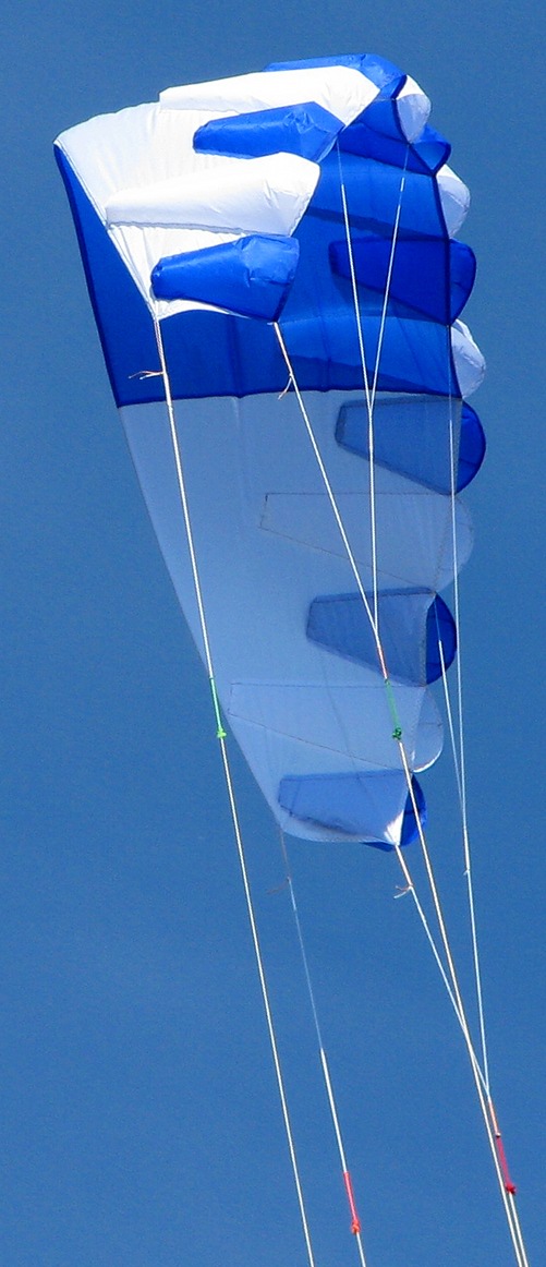
Maeko a sparless single skin SLE sled using tailored bumps on the leading edge to maintain canopy shape. It is lighter, uses less material, and is easier to make than a standard parafoil.
- Flat aspect ratio: 5.1
- Area: 1 m2
- Tip to Tip: 225 cm
- Center chord: 57.4 cm
Maeko is a minimalistic soft kite with nice flying characteristics. It is a result of the experiments done with Foil Nose 3.
Design Highlights
The combination of four key features come together in the Maeko design:
- Tailored leading edge bumps.
- All flat sewing.
- SLE bridle.
- Load and sheet tension lines.
In detail:
Tailored LE Bumps
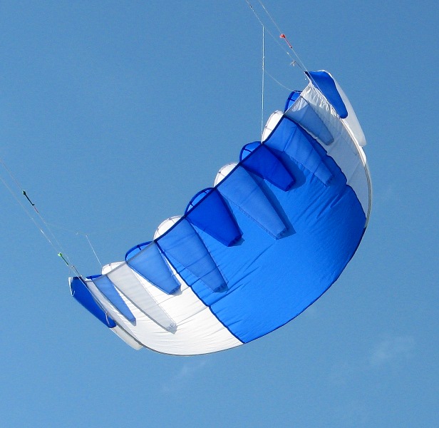
Both Yagu and Foil Nose 3 use LE cell openings which are perpendicular to the font of the kite. This is done for construction simplification, but is aerodynamically suboptimal. A judder, reminiscent of a flat sheet being held facing the wind, can be felt as the air alternates between being spilled above and below the canopy when flying these models close to the edge of the window.Maeko uses a tailored cone "bump" to create an aerodynamic shape which is more pleasing to the wind.
The top of the picture shows the opening of the bumps is 45° to the front of the kite, more like a normal airfoil. The bumps are roughly conical in shape. They are sewn to the canopy in a straight line.
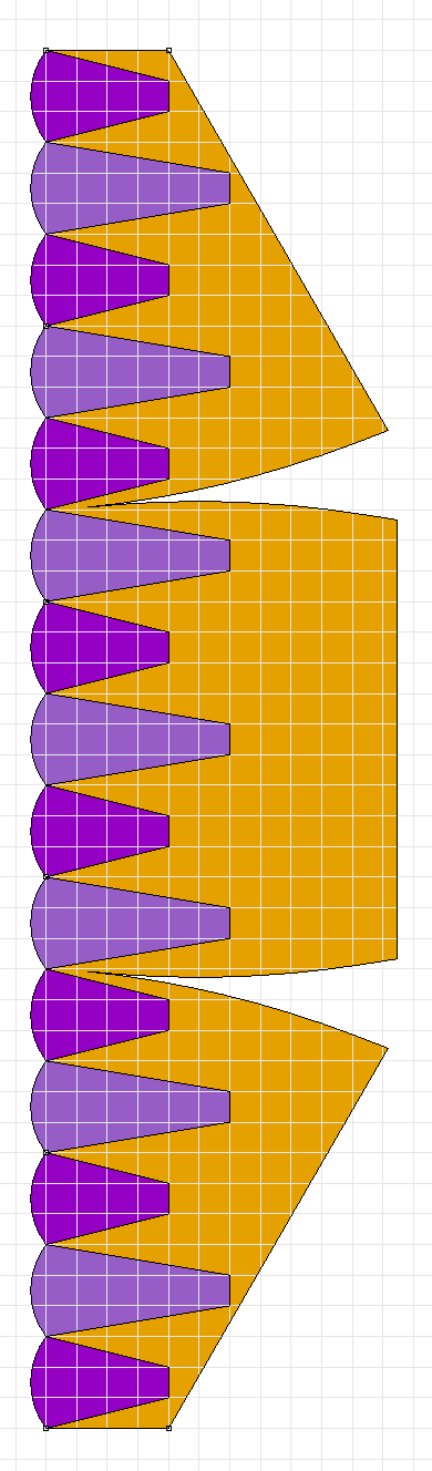
The shaping of the bumps is done with curved notches in the leading edge. A long and short bump is shown below before sewing creates the three dimensional shape.
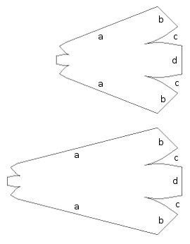
The curved edges 'c' are sewn together to form a straight leading edge made from 'b' and 'd'. The small end of the cone is treated similarly and sewn to the canopy. Line 'a' is the main sew line to the canopy. This produces the bump shape shown in the flying Maeko above.
Two sizes of bumps are used to prevent the chamber termination "spanwise wrinkle" problem described in Foil Nose 3. They also fit well with the narrowing span at the tips.
All Flat Sewing
In a typical foil kite, sew lines having differing curvature must be joined. For example, sewing the top part of a rib (curved line) to a canopy (straight line). For me, this often results in discouragement at the end of a sew line when the ends of the sewn parts do not match. I have not mastered the skill of preventing parts from creeping when sewing non-matching curves.The Maeko design only sews curves to matching curves. This allows parts to lie flat against each other during sewing. Part creep is entirely eliminated by temporary tape applied before sewing. For example, when sewing the bumps in the picture above:
- Fold notch 'c' in half so both the corners and bottom of notch match. Looking through the fabric, see that the curve matches exactly.
- Tape the edges 'b' and 'd' together to hold the fold in place.
- Sew along the curve line 'c'. Flip the part over and see that the back of the sew line is also on the curve line.
This is also true for the panel sew line joining the three sections of the canopy.
SLE Bridle
The Maeko bridle is SLE style for light weight and low windage. There are three bumps between each bridle point. The bridle is created using a double cascade with Prusik Knots for easy adjustment.
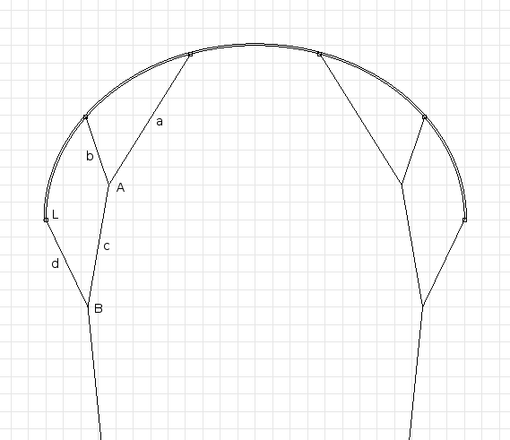
Segments 'a' and 'b' are part of a single line. The line is tied through the canopy in between two bumps on the leading edge. The LE load line (see next section) is also captured inside this tie for strength. A Prusik knot is used at 'A' for adjusting the length of 'a' versus 'b'.
In the same way, segments 'c' and 'd' are part of a single line. Loops are at each end of this line. One loop Prusiks to the top line at 'A' and the other loop larks heads to the load and sheet tension lines at 'L'.
At point 'B' is a short loop of line with a knot. The loop creates a Prusik knot for adjusting the length of 'c' versus 'd'. The knot is the front control line attachment point.
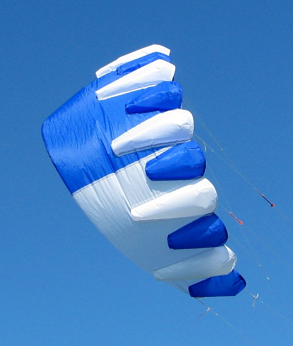
Load and Sheet Tension Lines
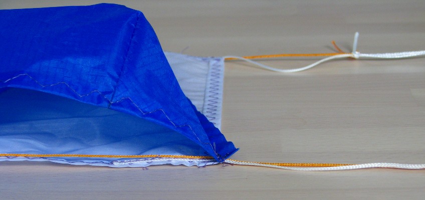
There are separate load (orange) and sheet tension (white) lines for both the LE and TE. The orange load line is a thick dyneema line designed to take the main load of the control lines. The white sheet tension line is used for tensioning the canopy fabric.In the picture below, the rear load line is in the tunnel formed from the hem fold in the TE. It is free to move inside this fold. The rear tensioning line is sewn along the line of the hem fold sew line.
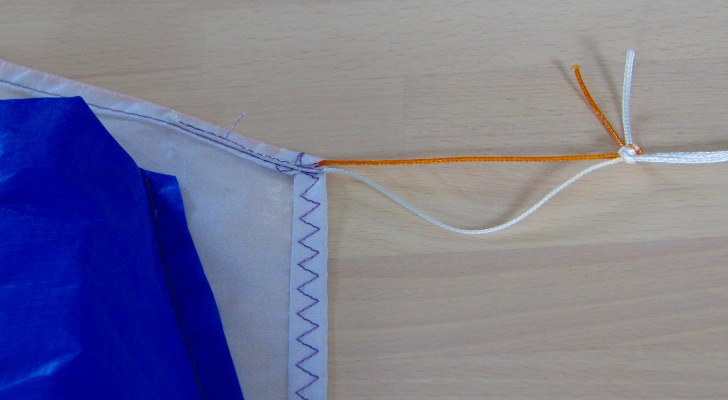
Below is the same configuration for the LE. The front load line is also free to move. It is inserted between the bump LE and main canopy LE after they are sewn together. The front tensioning line is sewn onto the canopy LE hem before the bumps are sewn on.
I considered using a thicker dacron fabric to carry the loads along the LE and TE instead of these dyneema lines. However, with mixed fabric there is a risk of non-uniform stretching/contraction causing unwanted bunching/warping as the kite ages. Also, having lines gives more adjustment opportunities. These waters are untested – the current setup is to tension each edge with light (1-2 kg?), wrinkle free force and tie matching load and sheet tension lines together.
Construction Plans
Anyone interested can build and improve this kite. The plans are free for download and personal use. The primary source is the Rhino drawing of Maeko. The plans are generated by a parametric design program like the one described in the Parametric Kite Design article.
Rhino is my favorite 3D CAD program. An evaluation version can be downloaded and used to print these plans. Perfect if you know your way around CAD and want to print templates to a specific paper size or have the luxury of plotting directly on ripstop.
A3 size templates were generated from the Rhino file above and saved in the Maeko A3 pdf design file. Great if you have an A3 size laser printer. The dxf file was created by exporting the Rhino 3dm file. Handy if you speak CAD, but not Rhino.
The lines shown in the plan are the sew lines and the outer edges of the fold lines. I use a 1 cm width between a sew and cut line. For a double fold hem, I use 1.8 cm width with a 0.8 cm fold in the inside and 1 cm fold on the outside. I use the longest possible stitch length when straight stitching, and the appropriate step length so that triple zig-zag ends up with 90° corners.
Below is an outline of construction. Ask away if you see ambiguities. If this design becomes popular, I will write a detailed construction article incorporating answers your questions to deflect email load.
- Before sewing:
- Create templates for canopy tip section, (half of the) canopy center, canopy bump sew lines, and both bumps. I create a second set of templates for the bumps so I can quickly draw both the sew and cut/fold lines instead of manually measuring from a single template.
- Double check that the templates are not "out of kilter", see tips below.
- Mark the fabric using the templates.
- Cut parts out of fabric. Wait to cut fabric from between the notches until after the notch is sewn.
- Main panel:
- Sew together the main panels. Use a window (or light table) to align the sew lines. Use tape around the hem to stabilize the material for sewing.
- Sew panel join hem flat to the top side of the panel. Ensure that "pulling apart" tension is applied to the panels while sewing so that the second sew line only flattens the hem instead of creating a new canopy shape.
- Double fold and sew the canopy tips with a triple zig-zag.
- Double fold and sew the leading edge with a triple zig-zag.
- Sew a tensioning pigtail line to each end of the LE.
- Straight stitch the double fold on the canopy TE to create a channel for the TE load line. You will be threading a line in this channel, so prepare the fabric join sections of the channel before sewing so that a line will not be snagged here when threading.
- Sew a tensioning pigtail line to each end of the TE.
- Bumps:
- Sew all bump LE notches. Sew line should go all the way to the edge of the fabric to make handling easier. Remember to align notch lines and use tape to stabilize as was done when joining canopy sections.
- Sew all bump TE notches. Same procedure as bump LE notch sewing. Notch fold should be on same side of fabric for both LE and TE of bump.
- Cut excess fabric out of notches. I leave about 1 cm to the notch sew line.
- Double fold and triple stitch LE of all bumps.
- Bumps to main panel:
- Mark the front of the LE every 15 cm.
- Use bump sew line templates and these marks to mark sew lines on top of canopy.
- Attach the TE of the bump to the canopy. Tape to hold position, then sew.
- Test by hand that the LE of the bump can reach the LE of the canopy following the sew path on both sides.
- Align the bump so the front of the sew line exactly intersects the mark at the LE of the canopy. Tape as necessary to hold exact position until sewn.
- Sew bump down starting at LE moving toward TE.
- Load line:
- Thread a load line through the TE tube. I use a line taped to a stiff long thin wire.
- Thread a load line centered above the LE hem but below the bump LE hems. I use a dull needle to make a space between the sewn layers and a strong thread to pull the load line through.
- Adjust the length of the load line by tensioning opposite tensioning pigtail lines and trimming load line to same length.
- Overhand knot end of load line and canopy tension line together.
- Bridle:
- Cut lengths of dyneema to satisfy measurements in bridle length table in the Flight section below.
- Cut short lengths of thicker dyeema for lower Prusik knot.
- Knot ends togeter of thicker dyneema section to create loop.
- Prusik knot this loop to line of lower leg.
- Create loops in ends of lower leg line.
- Prusik knot one end of lower leg line to upper leg line.
- Larks head the other end of the lower leg line to the LE tension/load pigtail.
- Sew both ends of the upper leg through the LE of the canopy and bumps, capturing the LE load line.
Construction tips:
- This should not be your first kite build. This is not a challenging design, but many details are glossed over. Sort out kite building principles by first building the very nice NPW9b.
- Important tip for template printing: the grid size is 1cm. If your device output does not reflect this then the templates will be, to use technical jargon, "out of kilter". Device output inaccuracies can be compensated for by pre-processing, but this is the subject of a future article.
- Build the 1.0 m2 shown here first. Building small before building large will magically be faster than building large alone. Mistakes made and improvements discovered during model size construction will pay time dividends. It's also nice to know a kite works in more than just the designer's back yard before committing expensive square meters of ripstop.
- Rule of thumb: All folds are toward the top of the canopy. For the canopy this means that the bottom is flat. For the bumps this means the curved joins and the LE hem end up on the inside of the chamber.
- Use light fabric colors for first builds. If using a dark color you need to plan on which side of the fabric to mark based on when it needs to be seen.
- Remove tape after sewing.
- Sew short bumps to the panel first, then go back and attach the long bumps.
- I attach the TE of the bumps to the canopy "back to back" so the TE flap of the bump ends up inside the bump.
- Because three panels are joined to create the canopy, the LE length may not end up being exactly 225 cm. As long as the length is not off by more than a few mm, the difference can be distributed equally between each cell when marking the LE for the bump sew lines.
- Sewing down the bump must keep the canopy material flat and not tension or wrinkle it. It is ok to have a little extra bump material when sewing arrives at the rear corner of the bump, but it is not ok to have extra canopy material.
- Tape is great for holding flat sewing pieces in position. However, avoid taping over sew lines and never sew through tape.
The last step is bridle adjustment and tuning, covered in the next section.
Flight
Here we setup the bridle and take Maeko for a spin.Some kite design programs produce measurements for SLE bridles. I have never tried these – do they work out of the box? If so, I am seriously impressed. The only way I could see this calculation being correct is for the design program to know how much lift is being generated on the canopy at every bridle connection point.
I do SLE bridle adjustment by making a drawing of the desired bridle shape, then fine-tuning based on how (the leading edge of) the kite behaves. Here are some bridle measurements taken from my current setup. Letter labels are from the diagram in the SLE bridle section.
| Length | |
|---|---|
| Line 1, section a | 78.5 |
| Line 1, section b | 49.5 |
| Line 2, section c | 48.0 |
| Line 2, section d | 58.2 |
| Prusik Pigtail B | 7.1 |
| Rear Extension | 66.5 |
These values are all 'ideal bridle' 'canopy to knot' or 'knot to knot' measurements. They include the canopy load/tension pigtail. Lines will need to be made longer than this to facilitate implementation, e.g., Prusik loops and slipknot connection to canopy.
There is an interplay between the length/tension on the rear lines and the SLE bridle settings on the front lines. Different lengths/tensions on the rear lines match different ideal front line bridle settings. Because of this, a bar (with the ability to lock the front line connection pigtail) is the preferred input method so relative lengths between the front and rear lines can be strictly controlled.
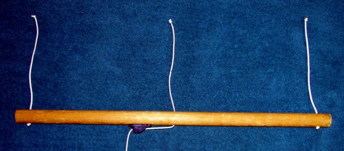
In the bar above, the front lines are connected to the central bar adjustable line and the rear lines are connected bar end lines. There are a couple of advantages with this setup:
- The kite can be landed (backed down) by removing the central line from the clamcleat and slowly letting it out.
- A similar maneuver can be done to reverse launch from a nose down crash.
- In an emergency, removing the line from the clamcleat will drop the kite from the sky.
Ok, with the preliminaries out of the way it is time for the bridle tuning procedure. Start with the bridle length setup shown in the table above, and the central bar line let out. Perform bridle adjustments to both sides of the kite equally.
- Start pulling in the central line until the kite launches.
- Near apogee, keep pulling in until part of the canopy collapses, then back off.
- Land the kite. Depending on which part of the canopy collapsed, a different adjustment is needed:
- If the top of the canopy collapses first, use the Prusik knot at 'A' to lengthen 'a' (shortening 'b').
- If the shoulder of the canopy collapses first, use the Prusik knot at 'A' to lengthen 'b' (shortening 'a').
- Repeat until canopy collapses evenly under a shortened central bar line.
Read the "AOA indicators" section of the Yagu article for more information about attack angles of individual canopy sections.
What about the lower Prusik knot adjustment? It controls two things:
- How 'open' the SLE kite is.
- The twist angle of the canopy tip.
Use Prusik 'B' to shorten 'c' (lengthening 'd') to make the kite more 'open' or 'flatter'. This will cause the tip to be more twisted (have a higher angle of attack) when the TE line is tensioned. The converse adjustment will make the kite more "C" shaped.
Each lower Prusik knot setting will have a different matching upper Prusik knot setting and rear line length/tension setting. Thus, the upper Prusik knot setting procedure will have to be carried out whenever the lower Prusik knot position is changed.
See flying angle picture below. The game is to make bridle adjustments giving the highest possible flying angle without canopy collapse or other bad behavior under normal flying conditions. I got Maeko to go this high in about 10 minutes of fiddling with the bridle and rear line tension.
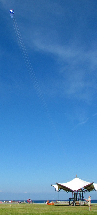
You can probably do better! Gain world fame: send me a nice picture and I will place it here for others to admire.
Maeko pulls harder than its size would indicate. Single skin nature: all of the canopy is being used. There is no trailing edge section "just along for the ride" like some dual skin foils.
Troubleshooting
After a crash, the central canopy TE may fold behind itself. A couple of sharp pulls on the TE lines will clear this.Before the first test flight, I was concerned that cell openings may fold inward. This is never a problem in practice. I saw this one time when a bridling problem (see next item) caused a part of the canopy to fly at the wrong angle. But otherwise, this aspect exceeded expectations.
The below picture shows a bridling problem that appeared out of nowhere during the second day of flight. Look closely at the right hand side bridle. There is a straight line from the central canopy bridle connection point and the 'B' Prusik pigtail. The 'b' portion of the upper line is slack!
The root cause is the front line twisting the 'B' Prusik point so badly that the lower cascade is twisted and shortened. This causes the right half of the kite to collapse. I am a little bit puzzled at this behavior as I have never seen a kite line twist a bridle like this before. For now I will put bearing swivels at each bar line connection point.
Flying on handles will prove quite challenging because of the relationship between SLE bridling and rear line tension/length described in the Flight section. Best to stick to a bar.
Future
- Bigger. I was positively surprised how well this flew right out of the box. I will be making a larger version (with tweaks below) to power some of my wind driven activities.
- Bump TE corners. Having the notches in the middle of the TE of the bump made sew alignment harder than it necessary. Next design will have the curved notches in the corners.
- Shorter center SLE line. The 'v' bottom of the upper SLE descends lower than necessary. This line can be made shorter.
- Different bar setup. Experiment to see if routing both LE and TE lines to a central bar point would increase stability. Tip lines on the control bar can be routed to pull on the TE lines routed to the center of the bar.
- The above is a first step to an autozenith experiment. See if the above and TE tip point weighting or spar will induce autozenith behavior.
Maeko!
Your cries for video have not gone unnoticed. Right click this Maeko video link and select 'save as' for a high quality ogg which can play natively on Linux or using VLC on Windows. Cloud people can see Maeko first flight on YouTube.The video is from Maeko's first day of flight. My daughter Bianca is the pilot. Notice how much wind is indicated by the leaves in the tree. A lightweight kite like Maeko has a definite advantage in these conditions.
That is all. Ladies and gentlemen, start your sewing machines!
Related pages:
Foil Nose 3
Yagu