 |
 |
 |
 |
 |
 |
 |
 |
 |
 |
 |
 |
 |
 |
Movie 1 | Movie 2 |
Design perspective
The design uses the NPW shape, paneling and rolled nose. The idea behind the design is to have two 'stabilizing' lines at the nose of the kite to provide more support to the leading edge in order to increase the window before the nose folds. These two lines are connected to the center line of a kitesurfer style control bar. The main power (and steering) lines are at the wingtips.This kite is one variation of a single skin BLSL (bridleless sparless) kite.
This BLSL space can be divided up into three areas:
- All lines 'centered' around the tips: e.g. Tel's ESP3
+ Groundbreaking. Even the Sailwing needed a double surface to support the LE. - Main power/turning lines at tips, AOA line(s) at TE: e.g. kiteship
+ Stable kite, TE line has 'tail' stabilizing qualities as well. - Main power/turning lines at tips, AOA lines at LE: e.g. NPWC, ESP2
+ Less unsupported leading edge means a potentially larger window.
Hopefully the number of areas will expand as people try new things. For example, all previous work being be blown away by combining a BLSL kite with a SLE bridle (used in, e.g., the GK Sonic). The NPWC could be a considered a first step in this direction, as the two front lines provide support to the LE of the kite.
Kiteship
Kiteship makes a BLSL kite designed for the requirements of sailing. The TE line placement in this design is brilliant in that it controls the AOA while at the same time increasing the stability of the kite to the point where it is uniquely appropriate as spinnaker replacement. Their design is patent pending. Support kiteship in their quest to make this a commercial success. A greater acceptance of kites in the sailing community can only increase the number of toys we get to play with when boat sized R&D budgets are pointed in this direction.Building
Panels:
Prototype measurements:
- A: 160, wing panel width/height
- B: 124, wing panel bottom after trim
- C: 127, wing panel top after trim
- D: 90, middle panel top width
- E: 62, middle panel bottom width
- F: 204, middle panel height (depends on curve cuts, cut long and trim after sewing)
Cut and sew:
- Fold a square section of fabric corner to corner.
- Cut along this corner to corner line, creating wings in the form of an isosceles right triangle.
- Flip one wing over so that the orientation of weft and weave is symmetric for both wing panels.
- Orient the wing panel with one leg of the triangle along the X axis and one leg along the Y axis.
- Cut panels according to dimensions above, ensure a smooth blending from curves to straight lines. The curves are under-emphasized in the picture above. (I would be grateful if someone with artistic skills could send me a drawing to replace this one!) If the blending is done correctly, there should little straight line left along the sew line of the wing panel.
- Sew center panel to wing panels. Start from the bottom. The top of the panel should be trimmed to end at the beginning of the circular arch on the wing panel.
Flying line connections:
- Reinforce tips with a second layer of fabric.
- Trim entire perimeter of the kite with hem band.
- Add pig tails to wing tips on the hem band.
- Add pig tails to hem band on corner where top of middle panel is sewn to side panel.
- Add more reinforcement to pig tail attachment points to spread load evenly to fabric.
Flying
Bar and line Setup
Lines are 30m Spectra or Dyneema. 300kg for tip lines and 150kg for nose lines. Control input is via kitesurf style bar setup, 70cm wide. Nose lines are attached to bar center line, and tip lines are attached to bar ends. Note that nose lines need to be longer than tip line length. To compensate for an equal length line set, replace the bar center line with a much longer line having no stoppers, etc. and attach nose lines to this line.Launch preparation
Anchor center line to an immovable object. Verify that bar has enough 'out' travel so that the kite can flag fully out on the front lines when the bar is dropped. With an assistant holding the kite, verify that the bar has enough 'in' travel to let the kite collapse with no pull on the nose lines.Launch and flight
You will not be able to fly this kite without carefully following the below. For most people this means a frustrating day at the field followed by re-reading this and saying 'doh!'. You have been warned.Have bar fully out. Kite will flap about on front lines. Have assistant grab bottom of kite to stabilize it. Start pulling in on the bar until kite fills with air. With assistant continuing to hold on to bottom of kite, experiment with the range of travel between pulling in / kite folding and letting bar out / nose collapsing. This is the range of AOA to fly this kite. There is very little bar movement between luff (bar out) and stall (bar in).
Let bar out a small amount and call for assistant to let go of kite. As kite starts moving, pull bar in towards middle of range. If kite stops moving, repeat this 'let out to speed up', 'pull in to lock in' flying strategy. The kite will fight to pull the bar out. You must pull hard on the bar while keeping the bar within the small range of travel along the center line. If the kite wins this tug of war, it will immediately luff, possibly turning inside out. If 'inside out' happens, flip the bar over to maintain steering control (right will be come left, and the reverse). Wind window is maximized by maintaining good kitespeed while keeping the bar as far 'in' as possible.
Danger: do not use a stopper ball or other device to limit the 'out' movement of the bar. Letting go of the bar lets the kite flag out with no pull, impeding this creates a very dangerous machine.
Results and further work
On the day I flew, the kite wind window was surprisingly large (for this type of kite). Typical flying was around 45 degrees, but at one point the kite seemed like it was 75 degrees overhead. Large steering input was required. Small adjustments in AOA (moving the kitesurf style bar in and out) had a large effect. The kite was only flyable in a small range of AOA.Next experiment will be with nose ties along the leading edge of the nose and part of the wing in an attempt to control the nose profile shape and allow a greater AOA range.
Inspiration from the David Barish Sailwing, Tel's ESP series, Dave's kiteship kite (patent application), JC's 3-DY, and the npw9b topica mailing list.
2005-10-30
Made a new NPWC using JC's spreadsheet. pictures/movies below:
IMG_1374.JPG
MVI_1392.AVI
MVI_1393.AVI
IMG_1407.JPG
IMG_1430.JPG
IMG_1438.JPG
Wind: 7m/s. The only thing I am unhappy with is a 'fold' from the main power lines through the canopy which appears often, especially in hard turns. I also noticed this on the original model. I will have to do some canopy curve thinking about how to solve this...
2005-12-18
I have been tweaking the panel shapes of the NPWC. The wing panel is modified from the original NPWC: wingPanelV3.JPG
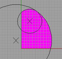
The center panel is a rectangle. (Not a modified rectangle like on V1) Using the scale of the wing panel drawing above, the width of the center panel is 9.2. The length is about 21.3 (best to cut long and trim after sewing).
For the purple/white NPWC model, the center panel is: 9.2 * 7.4 = 68 by 21.3 * 7.4 = 158. (each square is 7.4 cm) There is no 'E' cut on the center panel - it is a rectangle. The entire long side of the rectangular panel is sewn to all of the curved portion of the wing (which contains sections of both the small and large circle - everything colored purple is the wing panel). The fabric weft/weave should be aligned with the green/red lines.
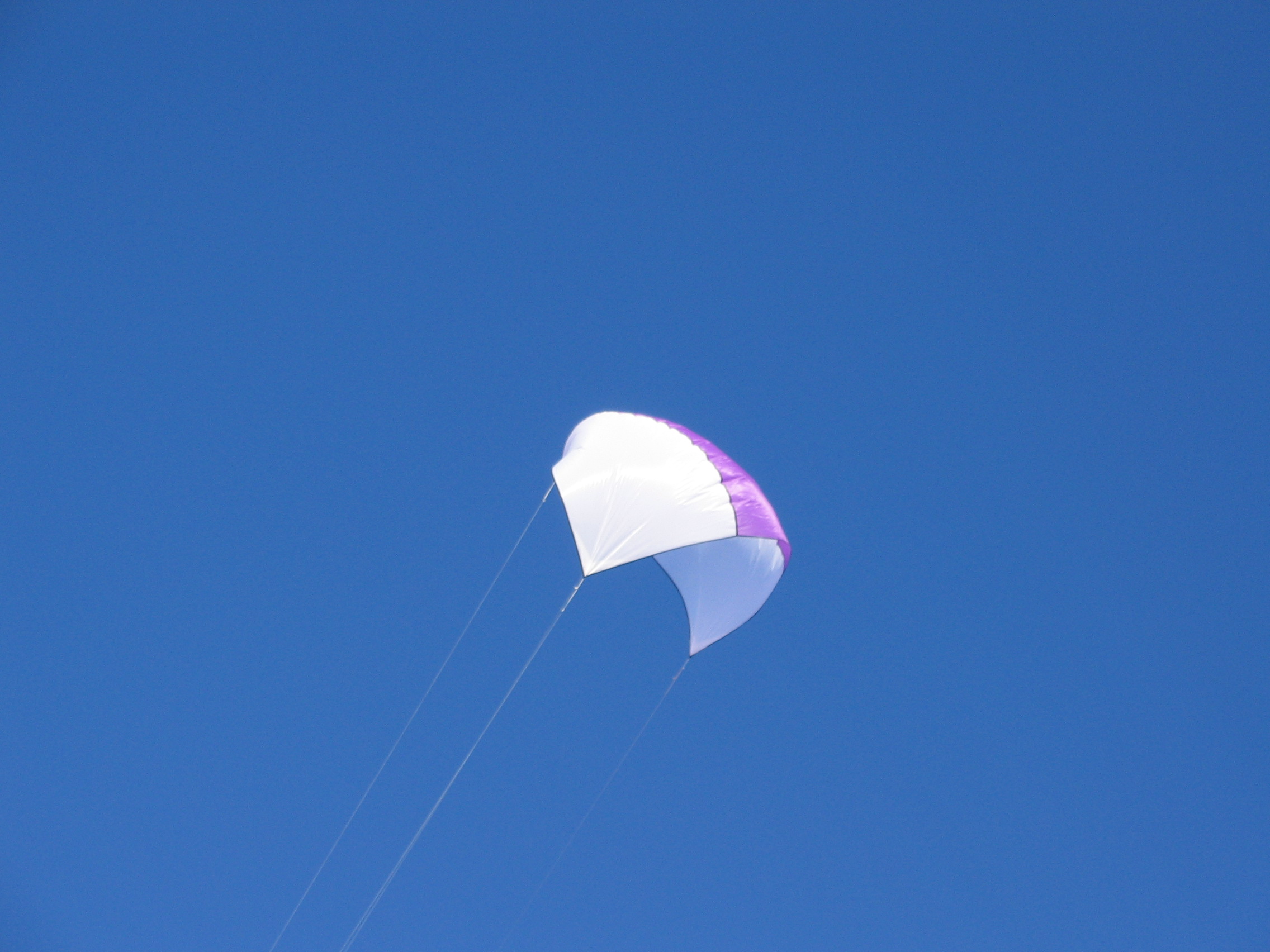
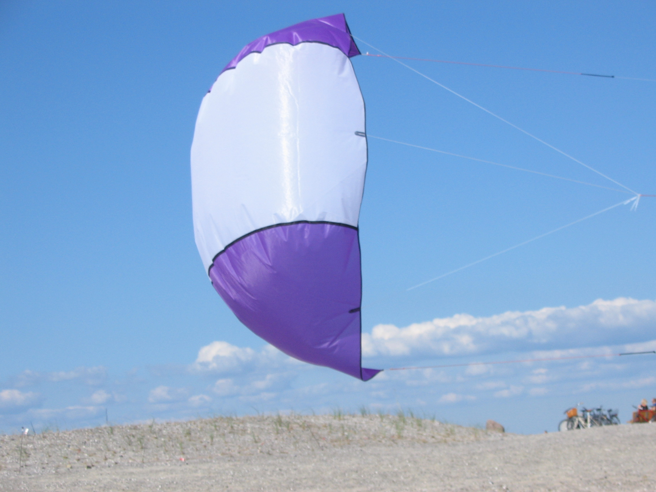
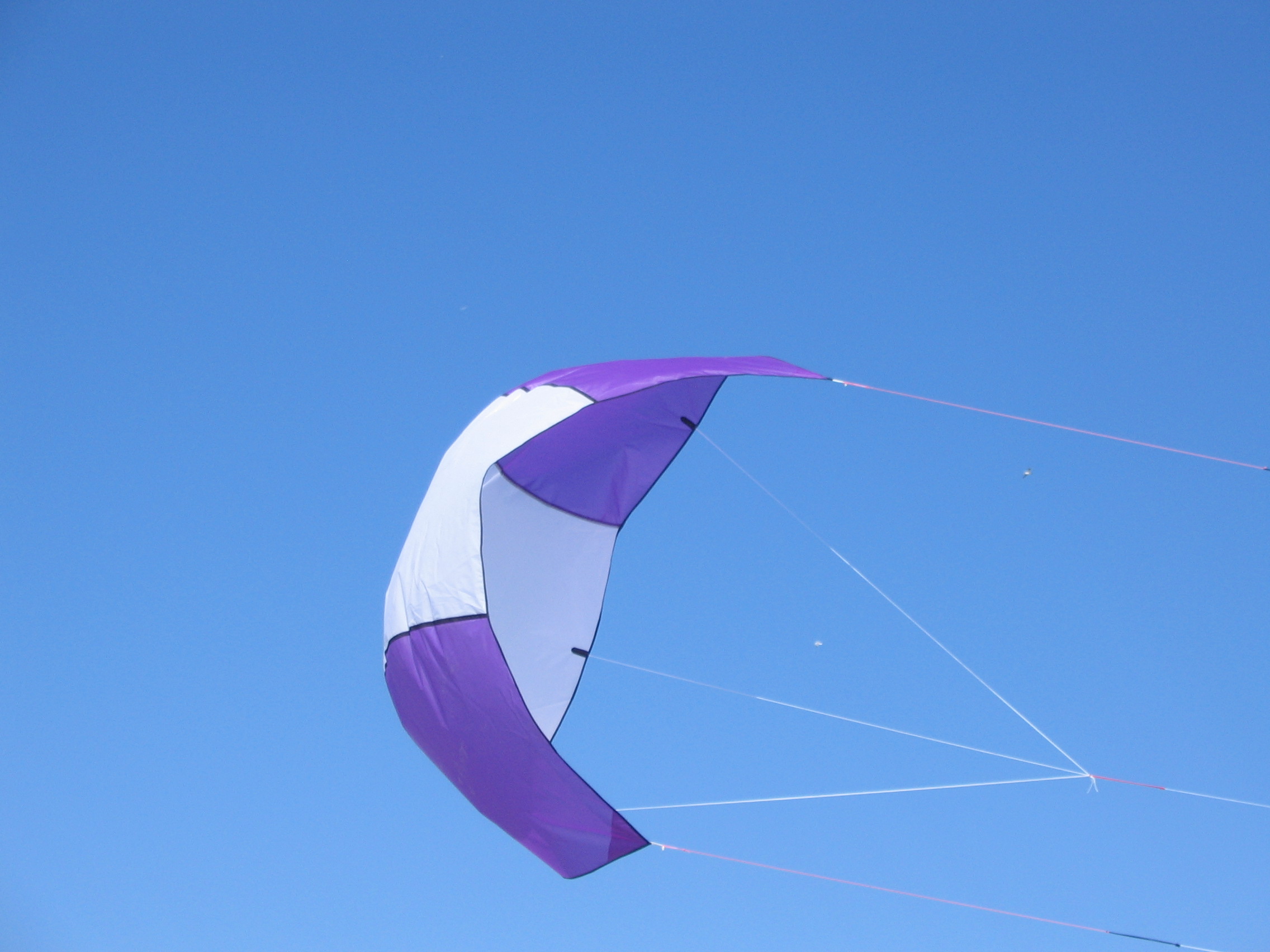
Here are some flight pics and a movie:
IMG_1580.jpg
IMG_1605
IMG_1607.jpg
MVI_1608.avi
The kite was built to a scale of 1 square = 7.4cm. Wind was blowing 7m/s. Not to many pictures as it was 0 degrees Celsius at the beach. Happy with this test flight, but still room for improvement. :-)
2006-7-2
NPWC v7
In comparison to the v3, the LE/TE ratio of this version has been increased. This gives greater tension to the front line and allows a more shallow canopy curve to be used. A simple bridle with a single front line moves this more twards an SLE setup.
Here are some flight pics and a movie:
IMG_2596.JPG Front view.
IMG_2627.JPG Rear view.
MVI_2681.AVI Flight movie.
The wind was very light, between 0 and 3 m/s. A more complete writeup to follow once this design is flown in stronger wind.
2006-10-15
Here is a flight pic of the NPWC v7:
IMG_2877e6.jpg Side view.
Picture taken 2006-9-5. The line angle indicates a L/D of 1.7. Take this with a huge grain of salt. My subjective experience was "It's straight overhead!" The picture may or may not have been taken when I had this thought. "Normal" flying angles were less. So, this picture is usless as a scientific basis for determining L/D. But it has been quiet for a while and I wanted to show at least something. :-)
2007-1-27
New experiments. Check out the NPWC v8 page.
2007-3-25
More experiments. Check out the NPWC Foil Nose page.
Have fun! Please send me your pictures, experiences, and modifications.