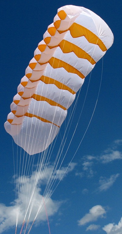
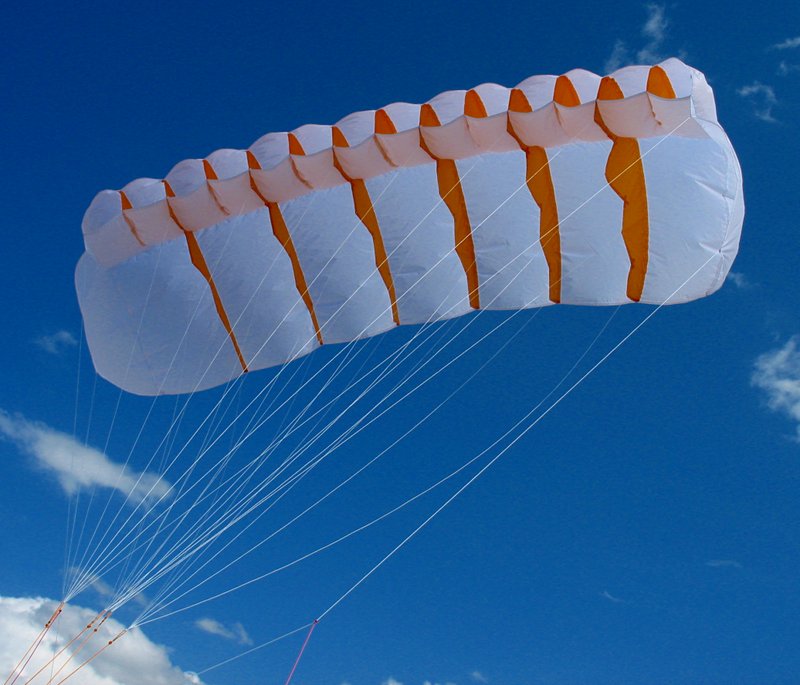
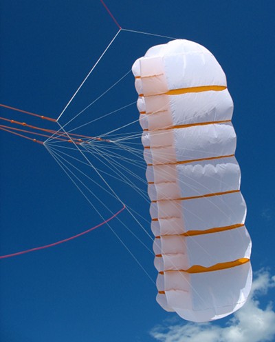
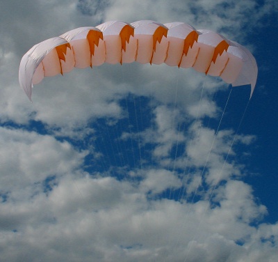
Volkite is a kite with two skin foil construction on the leading edge and single skin for the rest of the canopy. It is lighter and uses less material than a standard parafoil.
- Flat aspect ratio: 3
- Area: 1.5 m2
- Tip to Tip: 212 cm
- Chord: 70.5 cm
Working with a (partially) single skinned kite is illuminating because it clearly shows when a section of canopy is not not contributing to lift.
Inspiration
NASA-CR-108990, the last article cited in the Barish Sailwing article, contains a survey of current (as of the late 60's) parachute systems and their performance. The parachute with the best L/D, 4.3, was the Volplane, ranking above even the parafoils of the time.The Volplane is described in patent 3524613, filed April 8, 1968 and titled "Flexible Gliding Wing". William J. Everett, Jr. and the Pioneer Parachute Company are listed in this patent as well as the "Everett Parawing" patent 3428277. The Volplane patent is a "continuation in part of" the Everett Parawing patent, so it can be seen as an amplification and refinement of the ideas introduced in the patent describing performance improvements of NASA parawings.
The Volplane can also be seen on page 224 of The Parachute Manual by Dad Poynter, second edition, ISBN 0-915516-06-3. The Hornet, a similar partially single skinned parachute is also mentioned in this book.
The Beringer Parawing UL is another kite of the same genre. Jan Claes posted the Beringer article "Der neue Parawing UL" to the npw9b mailing list showing a foil-like kite where only the leading edge had two skins. Kai was kind enough to translate so us non German speaking members could read it.
Beringer holds German patent number DE9306467U on his creation, titled "Aerodynamisch geformtes Fluggebilde aus Tuch, Folie o.ä.". This patent can be found online at the European Patent Office. In the "Der neue Parawing UL" article he mentions that the concept may be used for non-commercial purposes. Beringer's book, "Parawings Mit erfolgreicher Technik zur Faszination", ISBN 3-88180-091-3, describes the Parawing UL along with a lot of other interesting designs and information.
The main differences between the designs are:
| Volplane | Parawing UL | Volkite | |
|---|---|---|---|
| Major rib length | almost full | full | full |
| Sections | 7 or 9 | 7 | 7 |
| Cells per section | 2 | 3 | 2 |
| Cell chord | 1/2 | 1/4 | 1/3 |
| Major rib bridle points | 5 or 4 | 6 | 4 |
| Planform | rectangular | tapered rectangle | rectangular |
It is interesting that the major ribs in the Volplane design do not go all the way to the TE of the canopy. Unsupported TE usually indicates flapping unless other design steps are taken. The Volplane has a valve system incorporated in the rear section of the lower skin allowing inflation from the rear of the cell.
Design
Not having access to the complete design of either the Volplane or the Parawing UL, I decided to create my own interpretation. Design choices are divided into profile creation, plan design, and bridling.Profile
The profile view below shows the layout of the mini-ribs, full length ribs, and the end pieces. Red dots and dashed lines show the control points for the splines which define the rib curves. The yellow dots are the bridle points. Section one is the mini-rib outline. Section two shows where it is cut off at the end allowing air passage between adjoining cells.
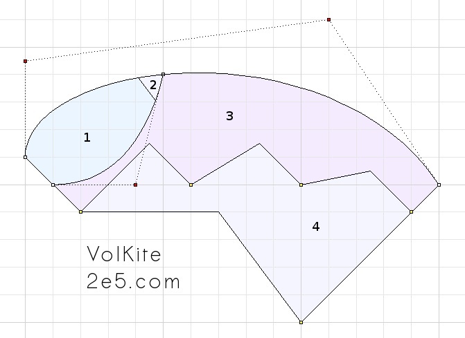
Sections 1+2+3 defines the area of the full length rib. In this prototype, there is no hole in the full length rib to allow airflow between the chambers.
The end pieces are the defined by the outline of sections 1+2+3+4. There are only two bridle point connections on the end pieces. Each full length rib has four bridle connections. Each square in the profile view is scaled by 4.7 for the full sized kite.
The chamber size is 1/3 of the chord. This lies somewhere between the 1/4 seen in the Beringer design and the 1/2 shown in the Volplane patent. The angle of the nose opening is 45° and sized to be 9% of chord length. The intention is for the cells to inflate quickly and retain inflation over a large range of AOA's without adding much drag.
There is no reflex in the profile. This makes the design more powerful but carries with it a positive moment which contributes to collapse. The profile curve is deep. This also makes the design more powerful, plus it reduces the amount of bridles needed across the chord. The extreme of this would be a NPWC style canopy which can fly without bridles directly from the lines.
In both the full length and end plate ribs, the connection to the TE is concave. This is shown by the last Bézier control point in the upper canopy creating an angle >90° to the TE of the rib fabric. I.e., the connection between the upper canopy and ribs is concave. Any unsupported convex edges would indicate flutter and loss of canopy inflation. The two most critical places to retain pressure/inflation are inside the LE cells, and at the TE of the canopy.
The following CAD code was used to generate the profile picture above:
; side view, 1/4.7 size of 1.5m^2 plan
; top skin
_Curve 0,1 0,4.5 11,6 15,0 _enter
; bottom skin
_Curve 1,0 4,0 5,4 _enter
; tips
_Polyline 0,1 2,-1 7,-1 10,-5 15,0 _enter
; ribs
_Polyline 2,-1 4.5,1.5 6,0 8.5,1.5 10,0 12.5,.5 14,-1 _enter
; min-rib cutoff
_Line 4,4 5.5,2
; bridle points
_Points 2,-1 6,0 10,0 14,-1 10,-5 _enter
The bridle points on the full length ribs are equidistant, every 4 units. The loading of the bridles is greater at the LE in static flight. The full length ribs are notched and have several small LE's just forward of each bridle point. In general, these are designed to be shorter that the edges just after each bridle point. The LE's of the last three bridle points are 1.5*sqrt(2) long. Outer bridle points have 90° corners, inner bridle points have blunter (>90°) corners. No cross ventilation holes for the full length ribs are shown in the profile drawing. The external parts of this rib (after the cells) are purposely solid to help channel airflow so it remains parallel to the chord.
Section 2 in the profile picture is the cut-off section of the mini-rib. This both simplifies the sewing of the mini-rib to top and bottom canopies and creates an air-channel to balance the inflation of adjoined cells. The banana which typically occurs a the narrow point where the rib joins upper and lower canopies is avoided in this design by omitting the narrow part of the rib.
The end ribs are larger than the inner full length ribs and have fewer bridle points. The larger size serves two purposes:
- Helping to hold the canopy inflated. Without the end plates, air would flow off the end of the canopy and not stay parallel to the chord.
- Increase the effective AR of the canopy. AR contributes to L/D, so canopy material can be synergisticly applied here.
Plan View
Below is the plan view. The 7 mini-ribs and the dual skin portion of the kite is limited to the first third of the canopy. The 6 full ribs extend to the rear of the canopy. Because the top skin wraps the curved ribs, it is actually longer than the projected chord would indicate: 112cm, or almost 60% longer than the chord. Each square in the below view is scaled by 23.5 for the full size kite.
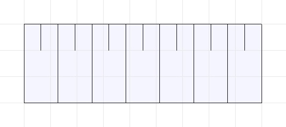
The plan view shows seven sections divided by the major ribs. This is not a magic number, it was chosen to be similar to the Volplane design. There could just as easily be more or less sections. More sections will give a greater AR and may generate a better L/D.
The following is the CAD code used to generate the plan view above:
; top view, 1/23.5 size of 1.5m^2 plan
;          (1/5 size of side view above)
; main rib
_Line 0,0 0,3
_SelLast
; 9/7=1.2857142857142858
_Array 8 1 1 1.2857142857142858
_SelNone
; mini ribs
_Line 0,2 0,3
_SelLast
; 9/14=0.6428571428571429
_Array 15 1 1 0.6428571428571429
_SelNone
; manual step, delete mini-ribs covered by main ribs
; LE, TE
_Line 0,3 9,3
_Line 0,0 9,0
The in flight canopy fabric bends in two directions. This plan shows an "unroll" flat projection only along the span. An "unroll" in both span and chord would show a plan which was less rectangular.
This plan does not show the line where the upper skin joins the lower skin. In reality, this line would be 1/3 the way from the nose, and the mini-ribs would be a little bit shorter, as they do not extend to the upper/lower skin join.
Bridling
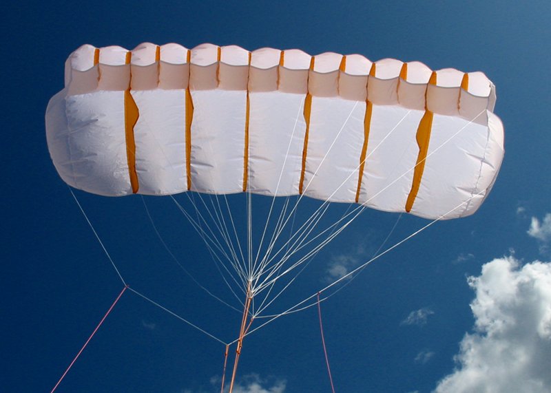
A view of the bridle is shown in the picture to the right. The nose chambers are to the left in the picture. The middle orange lines are used to adjust the profile shape across the entire span of the canopy. The orange lines at the top and bottom of the picture are connected to the end panel tip lines and used as a primitive way to steer the kite.
The initial bridle plan is chosen to ease tuning and testing of this kite. Bridles are grouped across the span of the kite, where the entire LE is in the first group, the second bridle point on all ribs are in the second group, and so on.
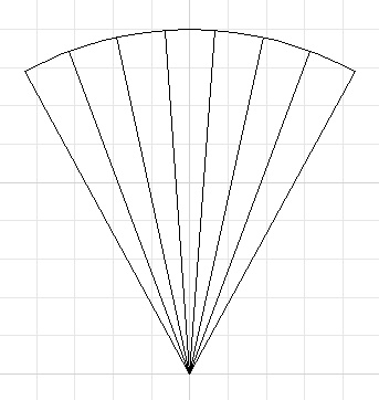
As seen below, having each bridle line the same length results in a crown canopy. Each bridle connected to the canopy is 211cm long. The physical construction is lengths of dyneema twice that long with ends tied to the bridle points and a central larks head connection to the orange bridle adjustment lines.
The image to the right is from the kite flying off a bar. The orange bridle adjustment lines are connected to the center line. The tip lines are larks head connected to the bar end lines for control. This is only done to test the overall design. Steering only through the tip lines gives inadequate control.
There are five groups of canopy lines connected to the orange bridle adjustment lines. Each group is numbered in the picture below. The yellow ovals indicate a sinle line which runs from the canopy to the bridle point and back up to the canopy. Group 5 is a special case of the lines used to control the tips. Since the lines are grouped spanwise instead of chordwise, it is very easy to adjust the overall AOA and also conduct depower experiments. A "finished" version of this kite would probably use chord wise cascaded bridles to minimize the amount of bridle line used. Using the pictured test bridle plan, two depower modes are accessible:
- Reduce camber of profile by shortening orange lines controlling groups two and three.
- Reduce AOA to (or past) the point where TE lines have no tension and canopy flutters by progressive reduction in groups two, three, and four.

As mentioned above, each white bridle line is 211cm long. The orange lines in the pictures is the cascaded bridle harness connected to the white lines and used to tune the kite. A cascade was used because it is straight forward to use Prusik knots in a cascade to adjust line lengths. The table below gives the equivalent straight line lengths, calculated from the start of the tip lines. Group numbers are the same as in the picture above.
- 18 (the leading edge group)
- 24
- 26
- 29
- 0 (the tip group)
This follows the normal expectation for a parafoil parachute: the leading edge lines are shorter than the TE lines. At first blush this looks like bridling for a negative AOA, but since the front part of the canopy creates more lift (creating more tension on the fronts than the rears), there is in fact a positive overall AOA in flight.
I don't expect these are the optimum, just the lengths I ended up with after a couple of hours testing. They are a good starting point, though.
CAD code for the bridle plan follows. This only shows the crown formed by the lines connected to the canopy, not the orange bridle adjustment lines.
; bridle plan, same scale as top view
; canopy curve when line length = canopy span: 180/π = 57.295779513082323 deg
_Line 0,0 0,9
_SelLast
_ArrayPolar 0,0 8 57.295779513082323
_SelLast
_Rotate 0,0 -28.647889756541161
_SelNone
_Circle 0,0 9
; manual step: trim circle to polar line array
_Zoom _Extents
Tips
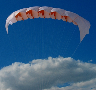
Tip lines can be adjusted independently. Soft kites should have "wash in" incorporated into their design, i.e. the AOA at the tip of the kite should be higher than at the center.The Volkite tip design was influenced by earlier NPWC work and uses only two lines. Testing revealed a couple of problems with this approach, the foremost being that there are not enough lines to support the shape of the fabric while adjusting the AOA of the tip. The picture above shows the front part of the tip bulging outward when the tip lines are pulled in to adjust the AOA.
The next two pictures shows a rear view the effects of tip lines at different lengths. The first is when the lines are shortened to increase the tip AOA. This does have that effect, but also "cones" the kite, bringing the sides of the canopy in and adding drag. An improvement to this would be adjusting the bridle of the major rib next to the tip so the AOA half way between the main canopy and the tip. However, this would not alleviate the "bulging of the tip" problem.
The second picture shows the tip lines adjusted to give a reasonable TE shape all the way to the tips. The AOA of the tip is likely too low, as I noticed some tip collapses when flying in this configuration.
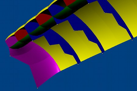
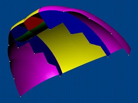
After obsessing about this for a few days, I made some models of tip possibilities, shown below.
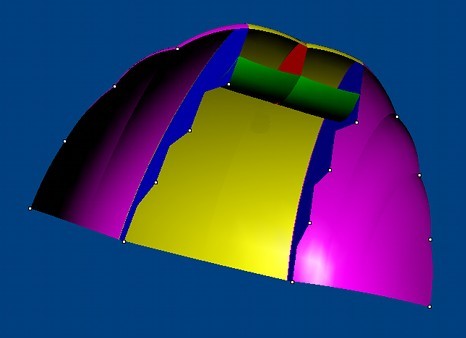
Models are color-coded according to part. Yellow is used for the main canopy skin, green for the bottom skin. Major ribs are in blue, and mini-ribs are red. The tips in their different designs are shown in purple. The white dots represent the bridle connection points.
Below is the current Volkite tip setup and then a configuration closer to a standard Volplane. The advantage to using more bridle lines at the tips is better control of the tip shape at various angles of attack and less air escaping across the tip.
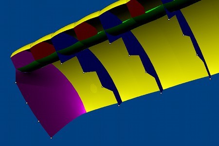
There are two things I don't like about the above tip configurations:
- There is a major discontinuity at the corners where the tip skin joins the cells. The top skin stops at the top of the last cell, and effectively starts again at the bottom of the same cell where the tip skin starts curving down. If the top of the tip skin is thought of as a continuation of the top skin, then this means that there is effectively a decrease in the starting AOA of the tips which has to be compensated for to achieve a tip AOA which is greater than the center part of the canopy.
- The span between the control lines across the canopy is suddenly larger in the tip area. When traveling across the canopy, each section is bridled. The exception is at the tips where there is about double the span between the tip lines and the next bridle points at the last major rib.
We can't totally trash the second configuration above, though. It was involved in the Volplane design which tested to a maximum L/D of 4.3, which is exceptional for a canopy which uses so little fabric.
This does not stop me from doing a mind experiment of the cross pollination possible between the Volplane and NASA Parawing world. Shown below is a Volkite with tips inspired from a typical NPW.
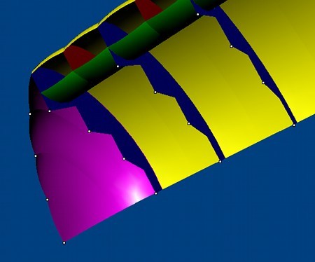
This addresses both dissatisfactions from the list above. There is continuity from the top skin to the tip skin. Bridling is more uniform, with the tip well supported from the final major rib and the LE lines on the tip skin.
What if the gene splicing is done in the other direction: take a vanilla NPW and add in some components to simplify the bridling and stiffen the LE? Something like the below might pop out, a NASA Parawing which uses a rib shaped load curtain to reduce the number of bridle points, and cells in the nose to allow lower AOA and resulting higher L/D.
The model imagined below also uses a canted keel, as shown in the best performing designs originally developed by the NASA engineers and documented on the NASA Parawing Research page. Testing would have to be done to see what cant angle to use as as the rib must be appropriately aligned to the under-wing airflow.
Suddenly, the mind explodes with possibilities for wide NPW's with multiple keels and ribs with progressive cant angles across the span. I will limit myself here to looking at the small corner where the top skin meets the tip skin. If additional stiffness is found to be needed in this corner, a cell extension could be used to create an additional chamber in the tip, pictured below.
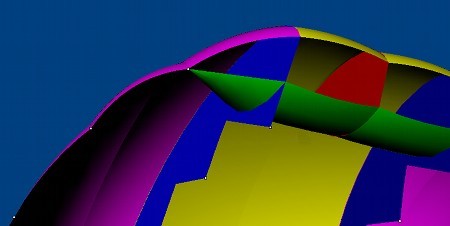
This cell extension is shown as open in the front, but could just as well be closed. Cross ventilation holes are assumed to be used as necessary in the designs above, and would serve to inflate any cell which is closed in the front.
There appear to be many fruitful avenues of exploration when considering the cross breeding between NASA Parawings and Volkites. This is not surprising as the Volplane patent itself was a "continuation in part" of the "Everett Parawing" patent, which describes performance improvements of NASA Parawings.
Future
From the past: Volkite robots are found in the Undersea Kingdom (1936), to the future.Plan of action ordered by time:
- Flight on longer lines with brake line steering. A test harness was used to test the kite and make basic bridle tuning. Tip lines were used as a primitive method to steer the kite. Flight under real conditions will help to determine further bridle tuning and effects of tip line length adjustment.
- Simplified design for construction. The current design is pretty simple, except for joining the cell sections to major ribs. This requires a sew join where the outer layers are straight lines and the inner layer is quite curved. It can be done, but requires skill and a lot of patience to get accurate and repeatable results. There is all the necessary information in this article for an experienced kite maker to recreate the current version this kite. The long term plan is a design for easier construction and a more detailed step by step plan which is more generally accessible.
- Major rib vent holes in the cells. There are currently no vent holes in order to highlight any cells which are not correctly oriented to the flow. There would be vent holes in a finished design.
- Various tip experiments outlined in the section above. If only I had lots of free time! :-)
- Volplane style valves on the bottom skin experiments. I am not sure if these would have any advantage in a kite design, but then again, there are lots of things I don't know.
- Volplane style major ribs which do not reach the TE. This will also simplify one aspect of the construction, as the TE hem fold is currently not created until sewing the major ribs is almost finished. I currently wait until this point to do the TE hem because it is impossible to accurately measure the amount of slip inherent in sewing a curved edge (the major rib) to the flat upper skin. If the Major rib does not go all the way to the TE, then the small difference in sewing slip can be absorbed by the non rib connected TE section.
See a a video of initial flight testing. It's a 14mb download. A smaller, lower quality version of the video is available on YouTube.
Related pages:
Everett Parawing
NASA Parawing Research
Barish Sailwing article